Technical Construction Drawing Services
The importance of technical construction drawings
- Have you recently had planning approved for a new development or new build home?
- Have you considered your next steps and how best to de risk your project?
- Do you know the statutory requirements for building regulation, health, and safety and CDM regulations?
- Or are you a practice that requires additional support to carry out technical construction drawings? With the residential, commercial, retail, and industrial or education sector?
- Have you considered how to appoint a contractor making sure your getting quotes like for like and most importantly value for money!
- Or are you contractor, developer and require accurate construction drawings to proactively and efficiently procure your trades?
Technical construction drawing (and the process of drafting) are a means of conveying information between engineers and manufacturers. Technical drawings complement digital CAD files, providing extra information that can’t easily be conveyed by a part’s shape alone.
This stage of the design process involves the production of clear and concise detailed architectural drawings and specifications, to be used for accurate pricing and by the construction team.
Carters is a CAD/Revit Company in UK offering Architectural Drawing Services for Residential, Commercial, and Industrial buildings. We create detailed and standardised working drawings and detailed drawings for apartments, single family houses, offices, health-care facilities, schools and universities, hospitality industry etc.
Construction Drawing Services are extremely complex and difficult to execute owing to the level of detailing and precision required for construction. We have comprehensive knowledge of building codes and construction standards for UK and countries in Europe which enables us to provide high precision and standardised output to our clients. We aim to provide high precision and standardised output. We present our working drawings in set standards with appropriate line weights, scale of the sheet, readable fonts, and color-coded layers.
What kind of architectural drawings do we produce: Depending on the project requirements we can produce.
- Floor Plans for space planning based on sketches or surveys.
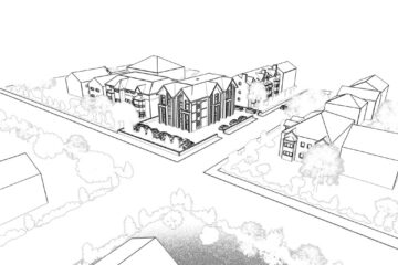
- Floor Plans & Elevations for planning applications based on sketches.
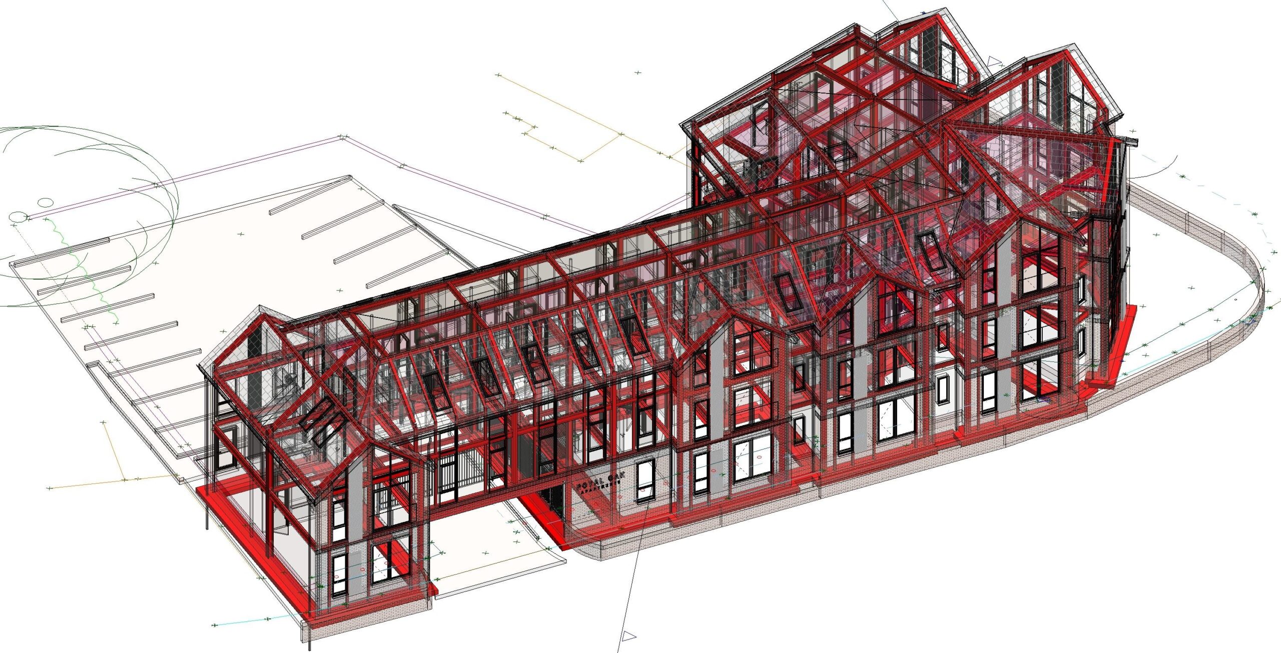
- 3D Building Information Models (BIM) based on 2D Drawings for construction.
What is BIM (Building Information Modelling)
A Building Information Model is an intelligent 3D CAD model. The intelligent model have additional information within the CAD model besides its geometric shape. For example, a steel beam model will include its actual section size, weight etc. or a wall will include attributes such as the actual brick size, thermal values, and cost per meter. The is a vast array of settings and custom attributes which can be added to the 3D CAD model. A further purpose of a BIM model is that it can be shared across the different disciplines. For example, the architects can create their model which is then imported by the MEP contractor to model all the mechanical, electrical, and plumbing services. The Building Information Model allows full coordination across all disciplines.
Why use BIM?
BIM largely increases the productivity of a project by reducing rework and errors. The BIM Model is shared across all parties involved which allows every discipline to design and plan their works virtually prior to construction commencing. Changes within the BIM model are excessively more cost-effective than changes on site.
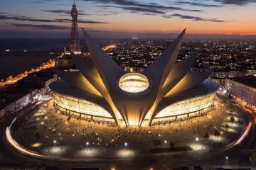
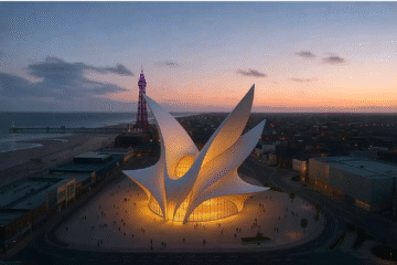
Besides producing a design that works and a set of construction drawings, BIM Models are also used for visualisation.
What can BIM be used for
• Visualisation
• Clarification of scope
• Coordination between different trades and services
• Clash Detection/Avoidance
• Design Validation
• Phasing of works
• Marketing Presentations
• Options Analysis
• Walk-throughs and Flythroughs
What BIM Services do we offer?
Carters Building Consultancy Consulting use Revit, AutoCAD, Plant & MEP and Advance Steel for our BIM modelling. Our BIM coordinators work closely with architects, mechanical & electrical engineers, and fabricators to ensure a successful project.
We produce BIM Models of:
· Commercial & Residential Properties (architectural models)
· MEP Services (Mechanical, electrical and plumbing)
· Steel Structures
· Process & Plant (Water & wastewater treatment, food and beverage, pharma and Oil, gas and petrochemical)
At Carters we have a wealth of experience working up planning applications and taking projects to the next level and carrying out technical construction drawings so projects can be fully understood, run smoothly, de risk unforeseen items, provide cost certainty when contractors are pricing for the works and making sure quotes obtained are like for like. Having detailed specifications for all elements of works for foundations through the roof tilling.
Additionally, when obtaining like for like quotes from contractors our technical construction drawing services can be used for making sure you are company with building regulations meeting the minimum requirements set out in the most recent approved documents.
Building Regulations and Planning Consent are not to be confused. These are different application processes, under different legislation and regulated by separate Council departments.
Most alterations, extensions and new building work needs to comply with Building Regulations.
Why we need technical drawings.
Technical drawings provide more extensive information than that in a typical planning drawing. Information conveyed through technical drawings may include:
- Tolerances for specific features
- Surface finishing requirements for specific surfaces
- Material requirements for specific components

Secondly, technical drawings can play a legal function. They are part of a purchase order and therefore part of a contract: if the manufacturer fails to deliver the parts as specified, the customer can use the technical drawing as evidence that the design has not been fulfilled; on the other hand, the manufacturer is protected from liability as long as it follows the technical drawing. (This does not apply if the CAD file is specified as the legal instrument over the drawing.
Furthermore, manufacturers often prefer to receive a technical drawing along with a digital file because they can make a fast assessment of aspects of the part such as its geometry, dimensions, and potential cost.
And finally, technical drawing internationally recognised way of communicating engineering instructions; there is no ambiguity, no confusion, and nothing that can potentially jeopardize the success of the project.
Technical drawing views and other features
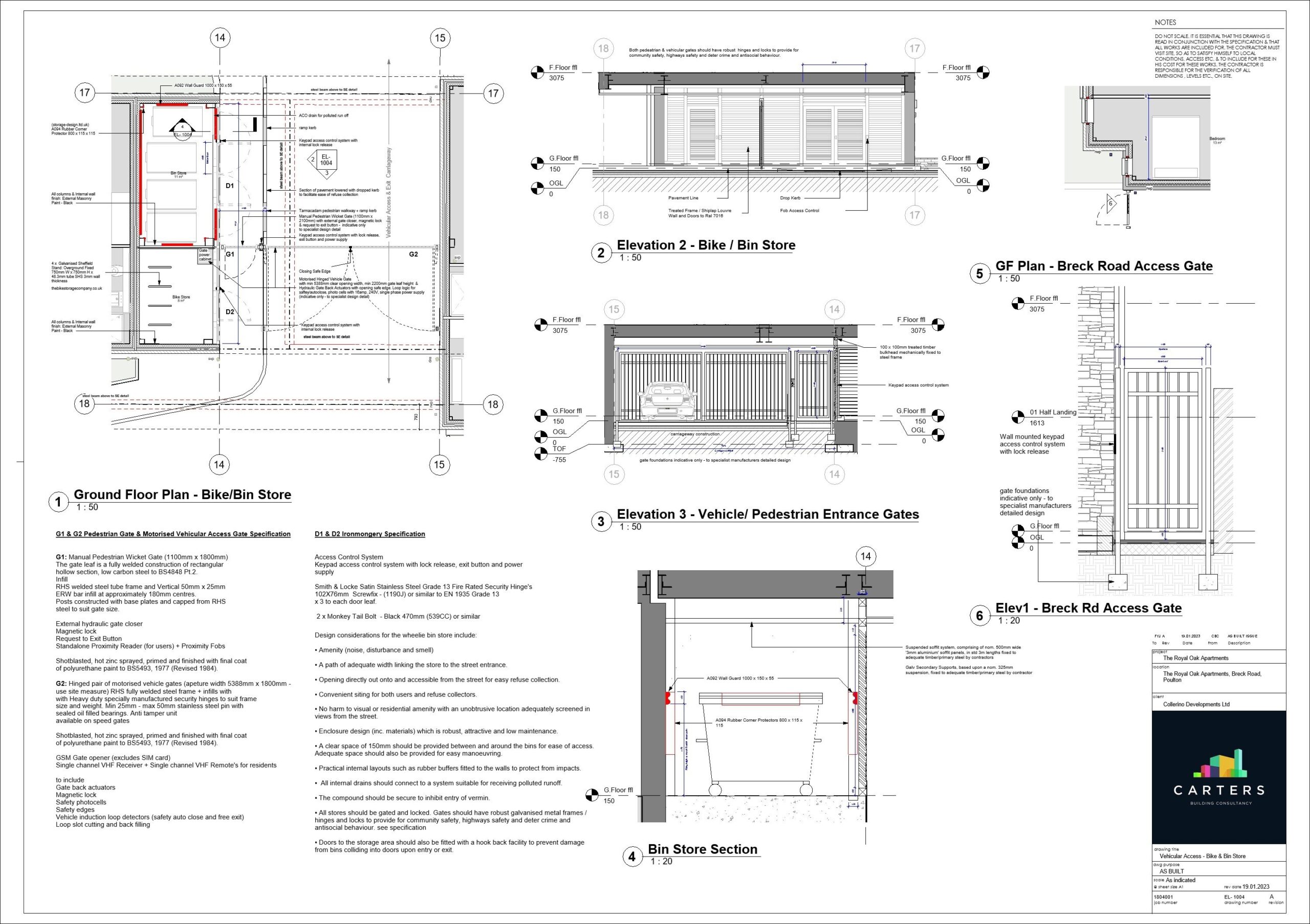
A finished technical drawing contains several different views of the building, allowing the contractor to easily interpret the architects and engineer’s intentions. A technical construction drawing will typically contain the following views and other features:
- Floor Plan: these will show the layout of the internal rooms, corridors, storage, stairways etc within a building.

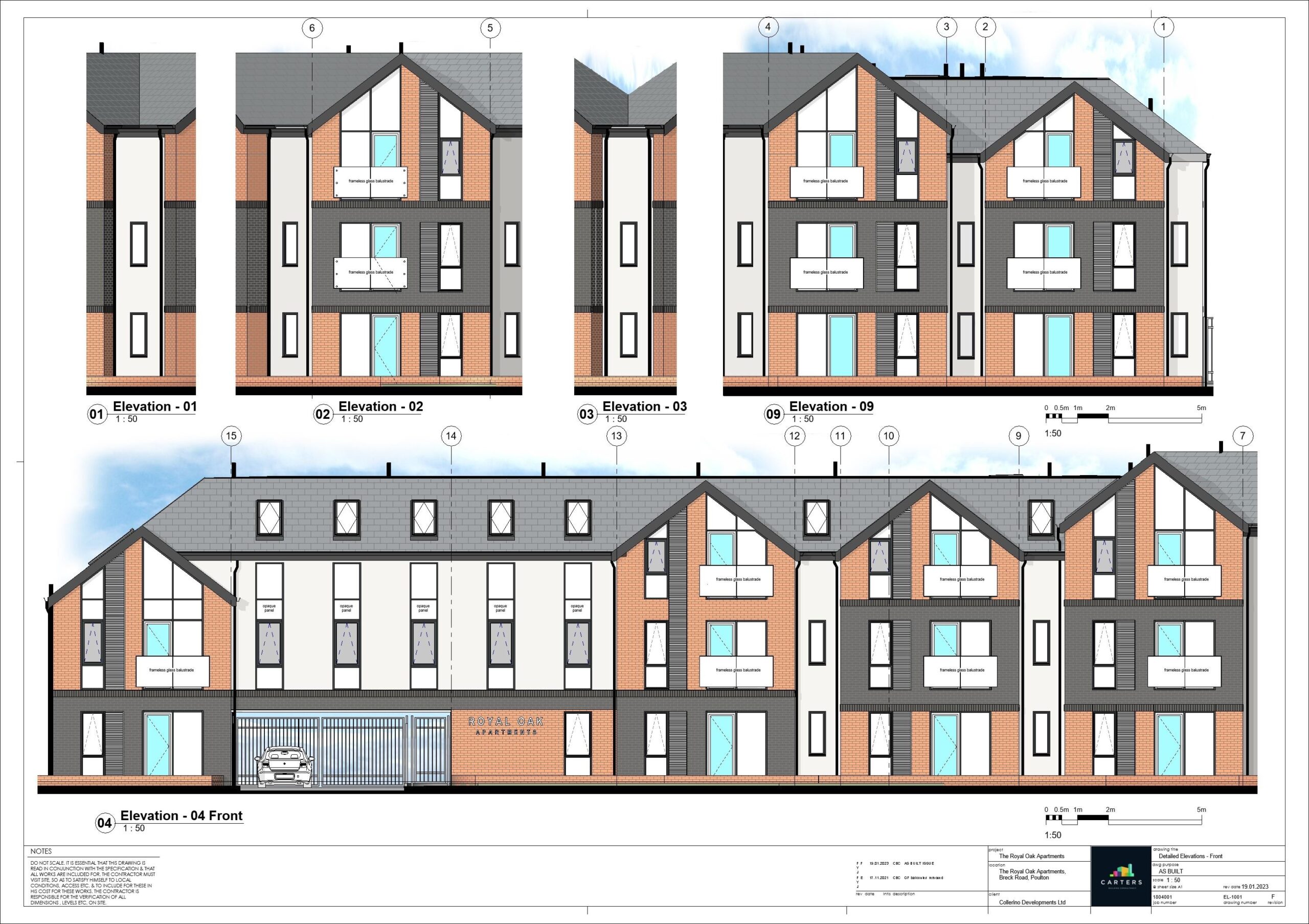
- Elevations: these will show the full building from different sides and angles and will provide the dimensions and structural features.
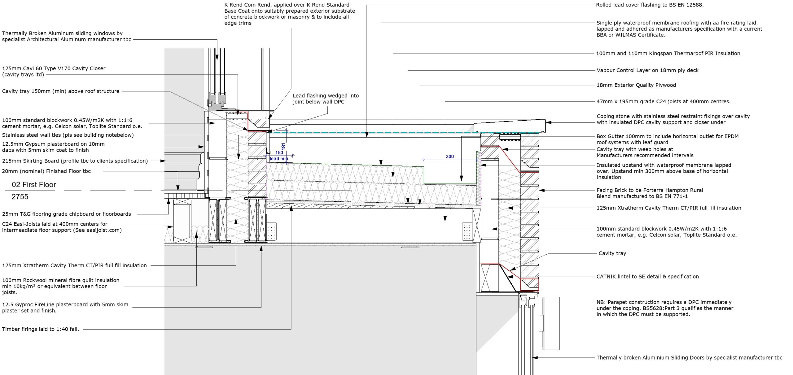
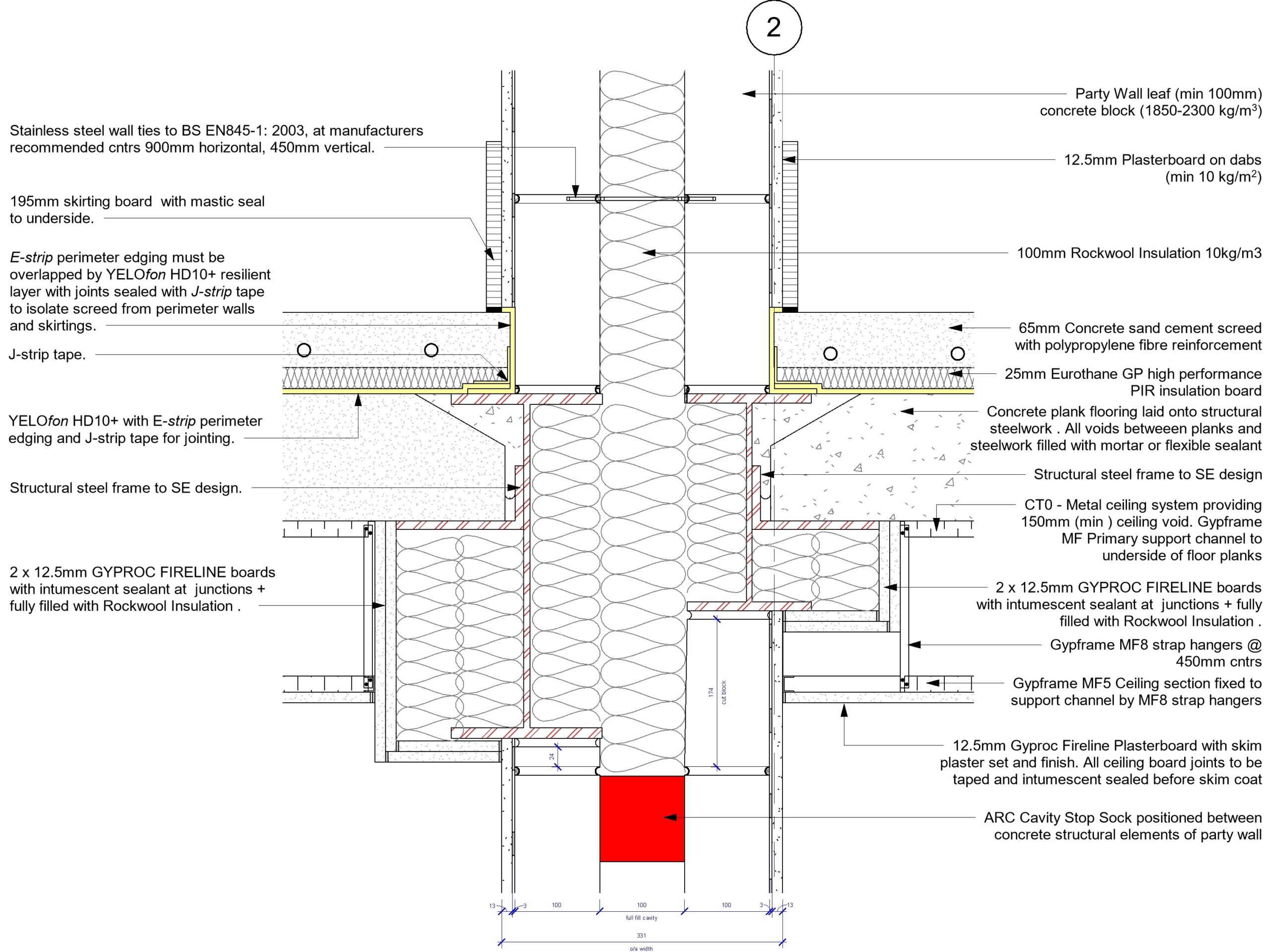
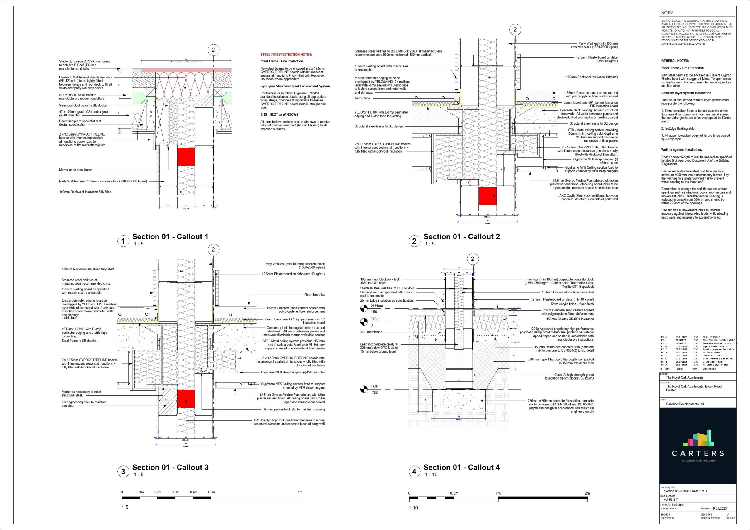
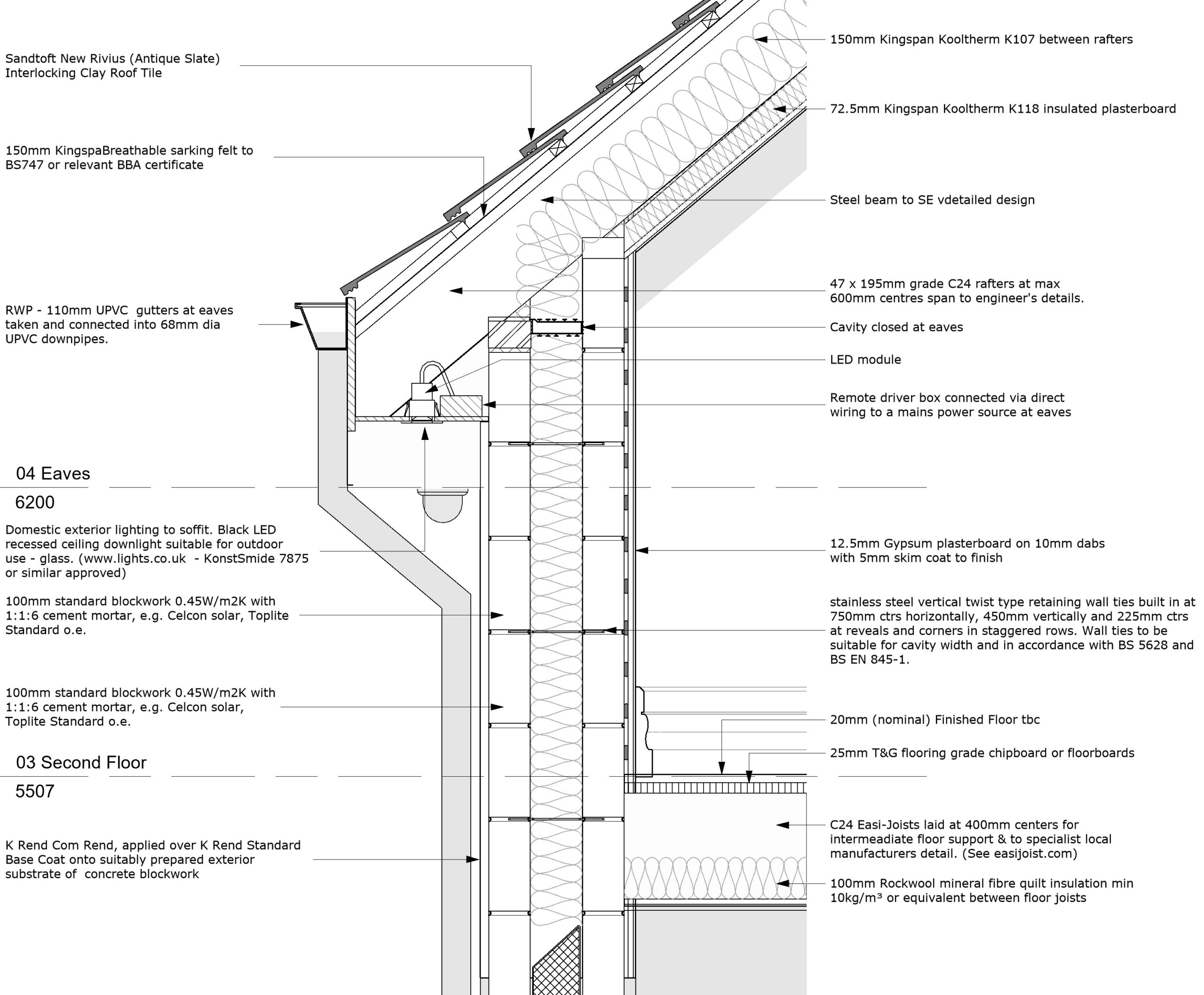
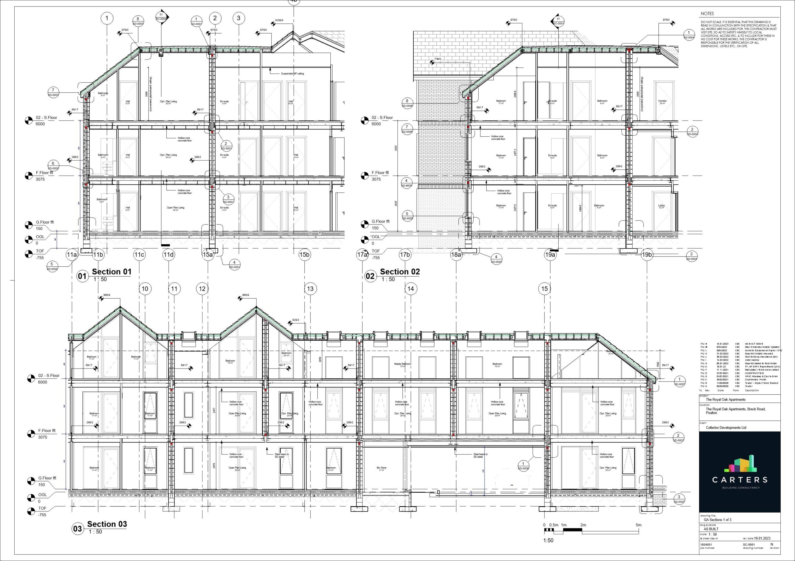
- Sectional plan: these will show the size and build of external and internal walls or partitions and may show elements like beams/columns or fire safety information.
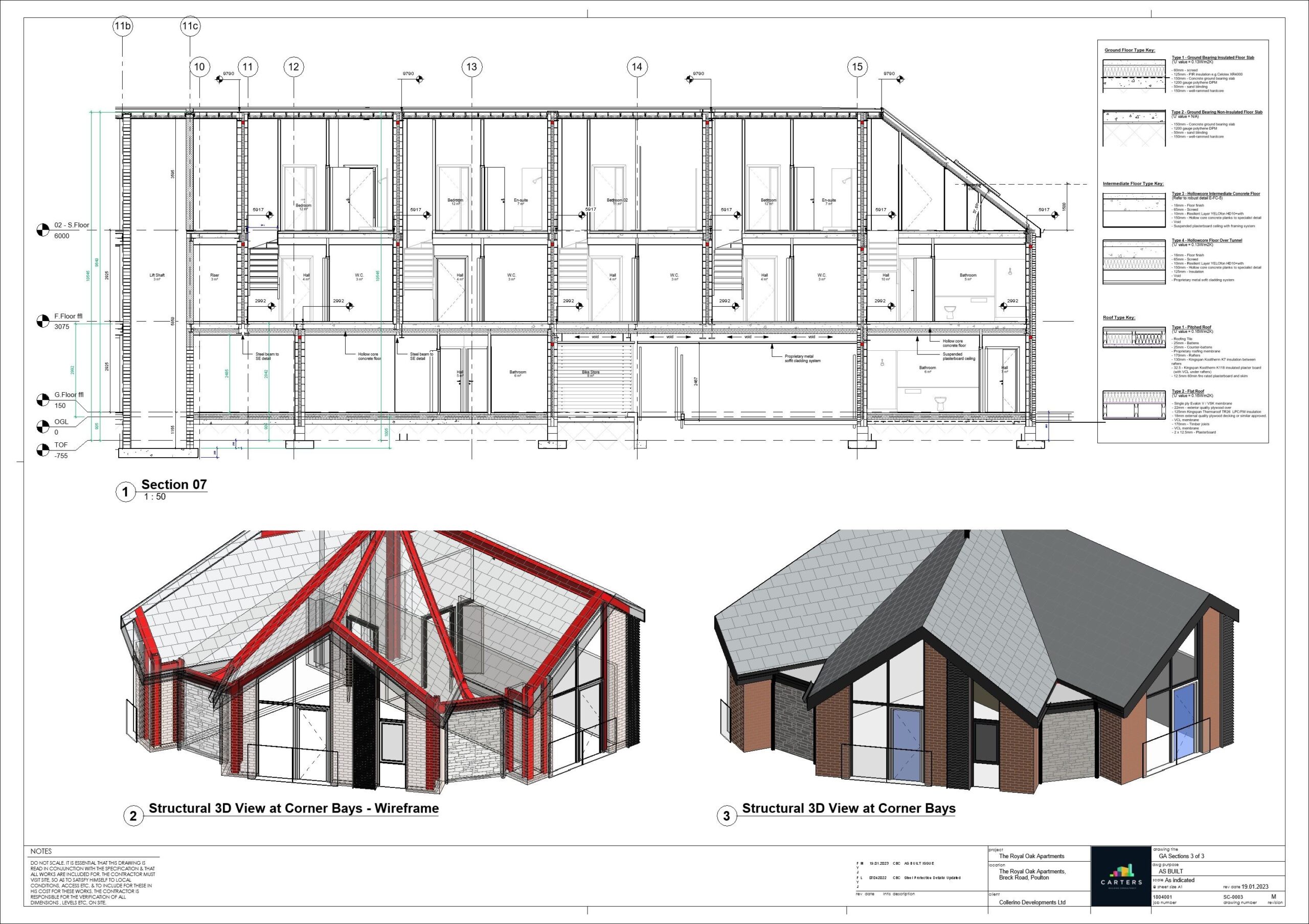
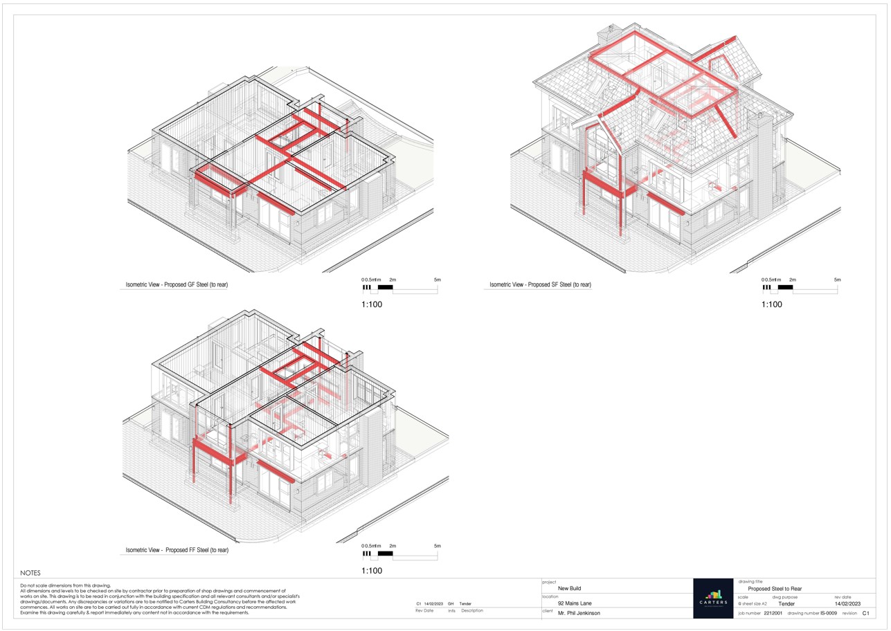
- Isometric views: An isometric or pictorial view shows the object rotated 45 degrees about the vertical axis and 35.264 degrees about the horizontal axis. The purpose of this view is to provide a three-dimensional view of the object with the illusion of depth.
- Section views: Section views show a cross section of the object along a specified cut plane. They are used to show internal details of a part and are usually placed in line with an orthographic view.
- Detail views: Detail views highlight critical or complicated areas of an orthographic view.
- Title block: The title block contains information such as the building name, company name, drawing number, material requirements, finishing requirements, colouration requirements, scale used, and standards used. It is typically placed in the bottom right corner of the drawing.
- Notes list: Notes to the user of the drawing may be included. These may be general notes or flag notes and can be placed anywhere along the edges of the drawing.
Carter's Building Consultancy has an excellent technical background and understanding of how elements are constructed from hands on experience. We are technically minded and can assist with any building regulation requirement.
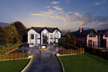
Whether you have already secured a piece of land, or you wish to replace an existing property with your very own bespoke-built apartment development, you can trust us to turn your vision into a reality.
What we can provide at a Glance:
- Stage 1 – Technical due diligence.
- Stage 2 - Feasibility designs and development appraisals;
- Stage 3 - detailed design and submission of planning applications;
- Stage 4 – Develop technical design, provide construction drawings, and submit building regulations applications. (RIBA Stages 4‐3);
- Stage 5 - Tendering works using a detailed schedule of works or cost plan with like-for-like quotations from contractors (RIBA Stages 4‐5);
- Stage 6 – Onsite contract administration/project management/ principal designer role (RIBA Stages 5‐6). Undertake on-site contract administration including issuing suitable forms of contracts and warranties, and;.
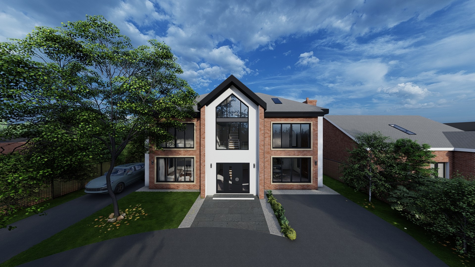
- Stage 7 – CGI and visualizations.
Anyone of the above stages can be selected individually or as a full turn key service offering. Carter’s have experience of many speculative schemes with partners and are happy to provide advice